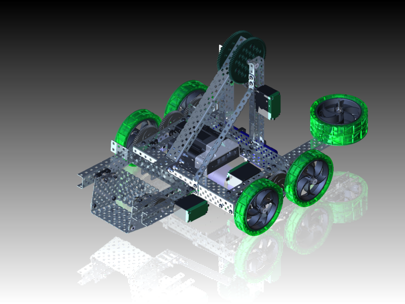
Testing of the scoop bucket prototype has determined that it is difficult to control the motion of the scoop. The direct drive mechanism from the motor to the lock bar is moving too quickly and the robot operator is having difficulty scooping up the game object. To resolve this design problem, a gear drive is designed and tested using Autodesk Inventor software.
In this project, there are seven videos including the Overview and Summary. To use the videos, click the link and review the content. Pause, rewind, fast forward, and stop features are available as the student reviews the content. The workflow in these videos includes:
- Modifying the scoop bucket frame.
- Modeling the driveshaft assembly.
- Modeling a gear assembly.
- Animating the assembly.
To be able to complete this unit you should have a basic understanding of the Autodesk Inventor user interface, navigation, and know how to work with Assemblies. For review, please refer to Appendix 9, 'Basic Inventor Commands Overview' for further information on these.
Overview:
Click here to download this video.
In this video, students will review the key phases required to design and model a gear assembly to drive the scoop bucket. To resolve a design issue with the motion of the scoop bucket, the frame is redesigned and a gear drivetrain is created.
Video 1: Model a Spur Gear Assembly
Click here to download this video.
Video 2: Model a Spur Gear Assembly
Click here to download this video.
In this video, students will modify the existing scoop bucket assembly. To accommodate the gear drivetrain, the scoop bucket frame is modified. A new frame member is added and two shafts with shaft collars are placed in the assembly.
Note: Metric equivalent of Imperial offset shown -0.625" = -15.9mm and -0.25" = -6.35mm.
Video 3: Assemble the Gears
Click here to download this video.
In this video, students will place the gears in the assembly. The initial gear drivetrain consists of a 12-tooth gear and a 36-tooth gear. The gears are placed in the assembly, constrained to the driveshafts, and the gear teeth are aligned.
Video 4: Complete the Gear Assembly
Click here to download this video.
In this video, students will add bearing flats and bearing pop rivets to complete the gear assembly. To hold the shafts in place, bearing flats and shaft collars are placed in the assembly.
Video 5: Add the Motor and Animate the Assembly
Click here to download this video.
In this video, the motor is added to the shaft and the gear assembly is checked to make sure it is rotating correctly. With the gear drivetrain in place, the original motor is placed in the assembly and constrained to the driveshaft. Checks are made on the rotation of the gears and shafts. When all parts are rotating correctly, an animation is created by driving an angle constraint.
Summary:
Click here to download this video.