There are 10 design videos to walk the student through the design and modeling of a 7.2V battery clip for the Clawbot. This battery clip will be integrated into the Clawbot assembly. Click on the title of each section to review the content in the video. Pause, rewind, fast forward and stop features are available as the student reviews the content. The workflow in these videos includes:
• Creating a new sketch
• Extruding the sketch to model the base
• Modeling the clips that retain the battery
• Adding holes in the base for attachment to the frame
• Engraving text on the surface of the battery holder
Overview
Click here to download this video.
In this video, all the key phases to design and model the battery holder in Autodesk Inventor will be reviewed. Modeling the robot in Inventor consists of assembling parts from the virtual kit of parts library, which can be found in Appendix 9. The key phases in the required workflow are reviewed in this overview video.
Video 1: Create a New Part and Sketch
Click here to download this video.
In this video, students start a new part file and create a sketch of the base. A new part file is created and the 2D sketch of the battery base is created. The sketch is extruded and a second extrusion is created around the perimeter of the base.
Note: A metric assembly template can be started by selecting the metric template folder. All the dimensions stated are in imperial; the metric equivalents are 5.5" = 139.7mm, 2.16" = 54.86mm, 0.19" = 4.83mm, 0.125" = 3.18mm.
Note: The files required for this activity must be downloaded, and data sets in Imperial and Metric units are available. The data sets provided will work for Inventor version 2013 onward. Download and unzip these files and save them into a new project folder.
You will also need to download and unzip the 3D print files for the Battery Holder project. Save these files to the same project folder as the data sets.
Video 2: Model the Battery Clip
Click here to download this video.
In this video, students will sketch and extrude a battery clip. Based on the design sketch, a 2D sketch of the battery clip is created. The sketch is fully constrained using geometric and dimensional constraints.
Note: All the dimensions stated are in imperial; the metric equivalents are 1.06" = 26.92mm, 0.18" = 4.57mm, 0.08" = 2.03mm, 0.15" = 3.81mm, 0.534" = 13.56mm, 0.4" =10.16mm, 1" = 25.4mm
Video 3: Mirror the Battery Clips
Click here to download this video.
In this video, students will mirror the battery clip. A second battery clip is quickly created using the Mirror command. Using a similar workflow, the ends of the battery holder are modeled.
Note: All the dimensions stated are in imperial; the metric equivalents are 0.625" =15.88mm, 0.9" = 22.86mm, 0.75" = 19.05mm
Video 4: Add the Holes
Click here to download this video.
In this video, students add holes to the battery holder. To assemble the battery holder to the robot, two mounting holes are added.
Note: All the dimensions stated are in imperial; the metric equivalents are 0.56" = 14.22mm, 1.5" = 38.1mm, 1"= 25.4mm, 0.35" = 8.89mm, 0.06" = 1.52mm, 0.194" = 4.93mm
Video 5: Engrave the Battery Holder
Click here to download this video.
In this video, students will engrave text on the surface of the battery holder. To customize the design, text is added to the battery holder using the Engrave command.
Note: The dimension stated is in imperial; the metric equivalent is 0.05" = 1.27mm
Video 6: Assemble the Battery Holder
Click here to download this video.
In this video, students will assemble the battery and battery holder. With the battery holder design completed, the 7.2 volt battery is constrained to the holder. The design is reviewed to ensure that there is no interference between the battery and the holder.
Note: In later versions of Inventor, the first component inserted is not automatically grounded unless you insert by positioning with the Right mouse button and selecting the 'PlaceGrounded at origin' option.
Video 7: Assemble the Battery Holder to the Robot
Click here to download this video.
In this video, students will place the battery holder assembly in the main robot assembly. The battery holder assembly is bolted to the robot frame using two cap screws and nuts.
Video 8: Document the Part
Click here to download this video.
In this video, students will create a drawing of the battery holder. A request is received for documentation of the part. A new drawing is created and five views of the part are created including three orthographic views, an isometric view, and a section view of the battery clip. Annotation is added to each view and the title block.
Video 9: Modify and 3D Print Battery Holder
Click here to download this video.
In this video, students will review the assembly of the Battery Holder, and make a few modifications before creating a file for 3D printing.
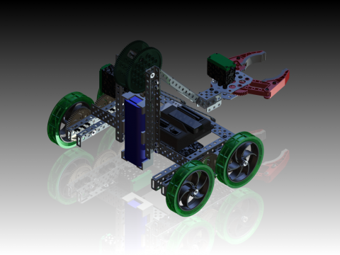
Here is an example of the 3D printed battery holder on a VEX robot:
Summary
Click here to download this video.
In this video, students will review the key phases required to create and model a custom designed battery holder. To design and model the battery holder, the workflow consists of the following:
• Creating a new sketch
• Extruding the sketch to model the base
• Modeling the clips that retain the battery
• Adding holes in the base for attachment to the frame
• Engraving text on the surface of the battery holder
Want to try more projects based on VEX robots and other exciting challenges? Click the link to access the Autodesk Design Academy.

